Grease Trap Parts & Interactive Diagram
Use this interactive illustration to prepare for a model-specific parts lookup. Grease interceptors vary widely. A label shown here does not prove that your unit has the same component, layout, service point, or replacement part.
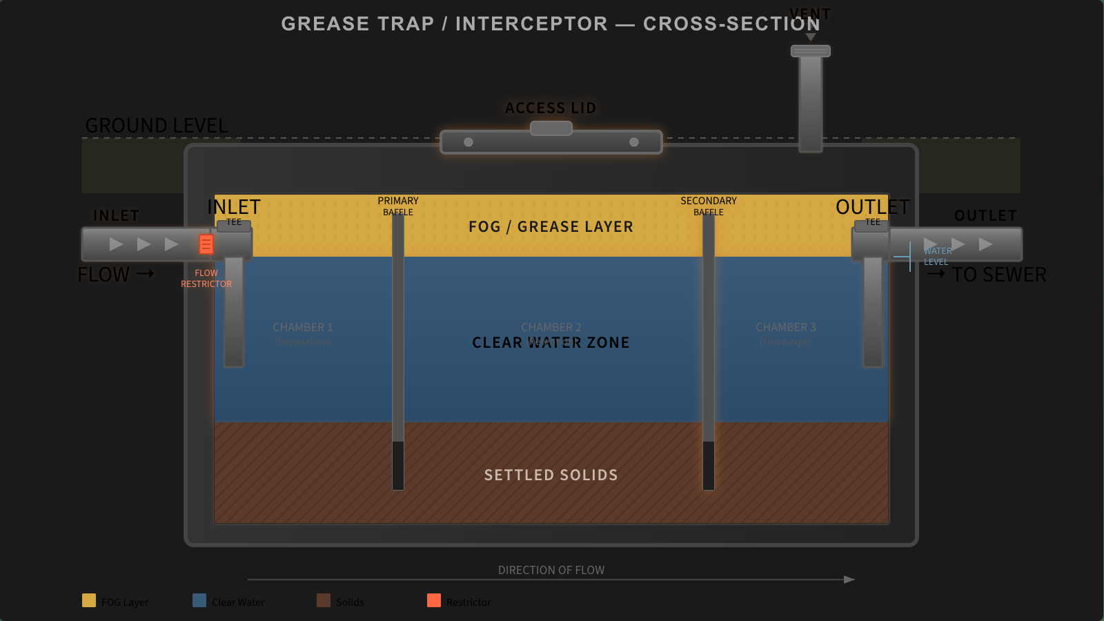
Illustrative grease-interceptor diagram
Select a possible feature to see what to verify.
Choose a label
Then compare the information with the equipment nameplate, approved drawing, and current manufacturer manual.
Before ordering a part or authorizing service
- Photograph the full nameplate without opening or entering the unit.
- Record the manufacturer, exact model, serial number, and installed options.
- Find the current manual, approved drawing, and parts list for that exact model.
- Confirm local plumbing, wastewater, permit, access, and inspection requirements.
- Ask the manufacturer or qualified service professional to confirm compatibility in writing.
Do not use a generic web price, lifespan, pipe size, service interval, or fullness percentage as a substitute for those documents. Local maintenance triggers vary, and manufacturer instructions are model-specific.
Frequently asked questions
Does every grease interceptor have these parts?
No. The labels are possible features, not a universal bill of materials.
Can this diagram identify a replacement part?
No. Use the exact model and serial information with the current manufacturer parts documentation.
Does a 25% cleaning rule apply everywhere?
No. Some local programs use a 25% condition, while others use different measurements or schedules. Check the authority serving the facility.
Can staff open or repair the unit using this guide?
No. This is not a service procedure. Follow the applicable safety rules, site controls, manufacturer instructions, and qualified-person requirements.
Official sources
- International Code Council — 2024 IPC definitions
- International Code Council — 2024 IPC Chapter 10
- Schier — product literature
- OSHA — Grease Trap Hazards
Fact-checked August 16, 2026. This illustration is not a parts catalogue, inspection procedure, or repair instruction.
Request Quotes from Local Grease Trap Pros
Tell us what you need. We review the request and may look for up to 3 available contractors within 75 miles. A match or response is not guaranteed.
A labelled cross-section you can print for the kitchen wall or send to your plumber. Free to use with credit to GreaseTrapLocator.com.